Skip to content
Skip to product information
1 of 2

Antminer L3+ U73 Step-Down Power Module DC Board Voltage Regulator Black Version

$3.00 CAD
$3.00 CAD $4.00 CAD
Sale Sold out
Shipping calculated at checkout.

Additional details

Shipping fees will be automatically calculated during the checkout process.

Reach out to us via the contact form for further information and assistance.

Secure checkout with
  • Visa
  • Mastercard
  • American Express
  • Apple Pay
  • Union Pay
  • Maestro
  • Bitcoin
  • Discover

About the Product

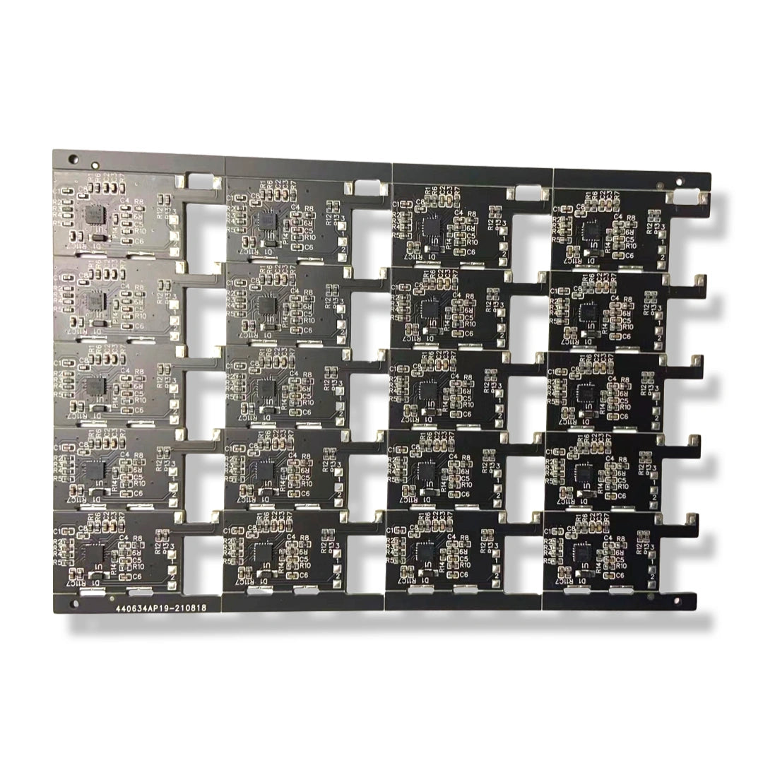
Antminer L3+ U73 Step-Down Power Module

If the L3+ power chip is damaged or there is no voltage in the voltage domain, this U73 module can be used for replacement. The L3+ U73 power step-down module can be used in the L3+ 10V step-down circuit control, on the Hash board with no material, serious oxidation, and lack of material. The module has a total of 8 external solder joints, 4 solder joints do not need to be soldered with wires, and can be connected to 3 external wires (the PIC cannot adjust the voltage) or 4 external wires (the PIC can adjust the voltage).

  1. GND: The negative pole of the power supply is grounded
  2. 12V: 12V input
  3. EN: Power on signal, connected to pin 3 of Q10
  4. HG: Controlled by the upper MOS tube, connected to pin 4 of the upper MOS tube
  5. LG: Controlled by the lower MOS tube, connected to pin 4 of the lower MOS tube
  6. DAOUT: Connect to PIC, can accept PIC voltage regulation
  7. FB(mos): Feedback input, connected to the large inductor L2, close to the MOS end
  8. SW(out): Connect to the output terminal of the large inductance L2


Category

Step-Down Power Module

PCB color

Green

Lead time

3-14 days

Reference chip

LM27402S 27402S

Area code

U73

MOQ

10 pieces

Condition

New


U73 module installation steps:

  1. First remove the original IC U73, and use a multimeter to check whether the original 3 MOS tubes have any problems. The normal resistance of the large inductance L2 to ground is about 40 ohms.
  1. Put the module on the inductor as above, connect the FB (mos) pad and the SW (out) pad to the inductor, and use an air gun and an electric soldering iron to dissipate heat.
  1. Connect GND to the left side of capacitor C943, as shown above.
  1. Connect 12V to the right side of capacitor C943, as shown above.
  1. Connect the HG signal to the 4th pin of the MOS transistor Q5, as shown in the figure above, pay attention to check whether there is a short circuit.
  1. Connect the LG signal to the 4th pin of the MOS transistor Q4, as shown in the figure above, pay attention to check whether there is a short circuit.
  1. Connect the EN signal to pin 3 of Q10. If this pin is not connected, it is a forced power-on, which will cause the control board to fail to turn off the power supply of the hash board.
  1. Remove the resistor R24, and connect the DAOUT signal to the position shown in the figure R24. If this signal is not connected, the PIC cannot adjust the voltage and can only work with a fixed voltage.
View Product Details

Got Questions?

If you’d like to learn more about us and our products, contact us!

Contact info

LYS-SZ

+86 182 1872 0821