Bitmain APW17 vs APW12: Choosing the Right PSU Family for Your Repair Workflow
For most of 2024 and into 2025, fleet operators running a mix of S19-class and S21-class Antminers carried two parallel PSU spare inventories. One for the Bitmain APW12 family — the workhorse PSU on the S19, S19 Pro, S19j Pro, S19 XP, and T19. One for the Bitmain APW17 family — the higher-output successor that ships with the S21, S21 Pro, S21+, and S21 XP. The two families share an architectural family resemblance but they are not interchangeable. The connector layouts differ. The voltage rails differ. The sub-version conventions differ. The failure clusters differ.
This guide is for the operator deciding how to allocate PSU standing stock across a mixed fleet, how to staff the bench skills, and which sub-versions to keep on the shelf. We work through the architecture differences, the sub-version landscape, the failure clusters per family, the cross-compatibility cases, and the decision matrix for fleet operators standardising their PSU stocking policy.
The shared architectural family
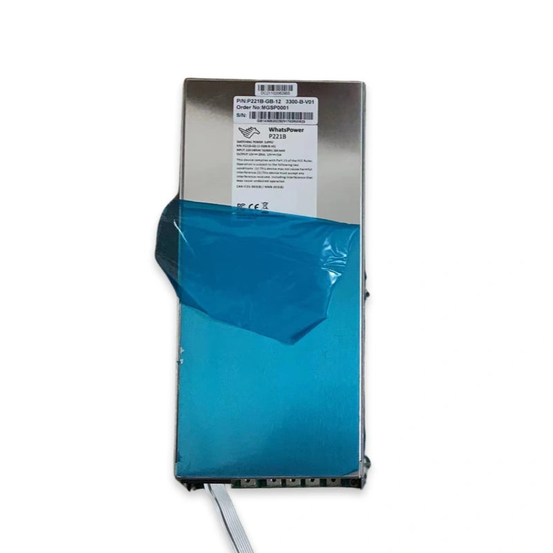
Both APW12 and APW17 belong to the same four-stage Bitmain reference design that has anchored the APW line since the APW3 era. Stage one is the EMI filter — fuse, MOV (metal-oxide varistor) for surge clamping, X-capacitor for differential-mode noise, Y-capacitor for common-mode noise. Stage two is the PFC (power factor correction) stage that produces the 410 V DC bus from rectified mains and delivers near-unity power factor. Stage three is the LLC resonant converter that isolates and steps the 410 V down to the secondary rail. Stage four is the synchronous rectifier that delivers the 12 to 15 V DC output to the hashboards.
The major control ICs inherit across the family : the L6599AD LLC controller, the PN8149W auxiliary controller, and the TEA2095T synchronous rectifier driver appear in both APW12 and APW17 designs, with variant revisions per generation. The MOSFETs differ : APW12 typically uses K39N60W5 and equivalents on the LLC primary side, with APW17 stepping up to higher-current-rated parts to handle the S21 family's elevated power draw.
The practical implication of the shared architecture is that a technician trained on the APW12 family understands the topology, fault-finding methodology, and oscilloscope-probing workflow for the APW17 family. The transition takes hours of bench time, not weeks. The differences are in the parts catalogue, not in the diagnostic logic.
The differences that matter on the bench
Output capacity
The APW12 family delivers approximately 3,300 W of usable output on most sub-versions, with the higher-end variants reaching 3,600 W. The APW17 family steps the output to approximately 3,600 to 3,900 W to feed the S21 family's higher load, with the highest-output APW17 sub-versions reaching above 4,000 W to support the S21 XP and S21+ hashboard configurations.
The implication is that an APW12 cannot reliably feed an S21 XP at rated power, even if a connector adapter could be fabricated. The S21 family is engineered around the APW17's output envelope, and substituting an APW12 for an APW17 on an S21-class unit produces sustained operation at the PSU's safety limits — a configuration that triggers protection cutoffs under thermal stress and shortens the PSU's useful life regardless.
Connector layout and sub-version conventions
The connector layout differs between the families and within each family across sub-versions. APW12 sub-versions APW121215 a/b/c and APW121215 d/e/f are not interchangeable with each other despite belonging to the same family — the connector pinouts differ, the firmware on the auxiliary controller differs, and substitution within the wrong sub-letter group results in protection-trip or, worse, miswired output. The APW17 family carries the same convention with its own sub-letter groups.
The practical operating rule is to stock spares by exact sub-version, not by family. A 100-unit S19 Pro fleet on APW121215a / b / c should hold spares of the same sub-letter ; the same fleet would not be served by holding APW121215d / e / f spares thinking they substitute. The same logic applies to the APW17 sub-versions. Our companion piece on the APW17 1215a repair components list walks through the sub-version-specific bill of materials in detail, and the companion APW11A1216-1a T21 components list covers the T21-specific APW11 sub-version conventions.
Cooling fan configuration
The APW12 family uses a single internal fan in most sub-versions, with a fan profile tuned to the PSU's expected load curve. The APW17 family steps to a higher-airflow fan configuration to handle the elevated thermal output of the S21-class units. Fan replacement parts are not interchangeable between the families. Fleet operators on a mixed S19/S21 deployment hold separate fan inventories for each PSU family.
Failure clusters per family
Field experience across the 2024 and 2025 operating seasons shows distinct failure clusters per family.
APW12 failure clusters
The single most common APW12 failure mode is the input-side EMI filter components — fuse, MOV, X-capacitor — degrading after extended exposure to brownouts and voltage spikes. Four cheap components account for roughly 80 percent of all field-reported APW12 failures : the fuse (a few dollars), the MOV (a few dollars), the X-capacitor (under twenty dollars), and the internal fan (under twenty dollars). The full repair components list lives in our APW17 1215a components list (which covers shared architecture conventions) and in the more general LYS APW12 reference catalogue.
The secondary cluster is on the PFC stage — the input filter capacitor and the PFC MOSFETs — which degrade more slowly but produce catastrophic failure when they do go. The PFC failure pattern usually presents as a hard fault rather than a gradual derating, and the fix typically involves the input capacitor, the PFC MOSFET, and the PFC controller IC together because the failure of any one of them usually damages the adjacent components.
APW17 failure clusters
The APW17 family's failure clusters track the APW12's pattern in shape but at a higher loading profile. The input-side EMI filter components fail on a similar timeline and the same four cheap components account for the bulk of routine failures. The PFC stage on the APW17 sees higher continuous loading than the APW12 because the S21-class units pull more power at the wall, which translates into a tighter MTBF window on the PFC MOSFETs and input filter capacitors. Operators stocking APW17 spares typically rotate the PFC MOSFETs at a higher cadence than they would for the APW12 family.
The LLC stage on the APW17 has been stable in field experience to date, with secondary-rail failures concentrated on the synchronous rectifier MOSFETs under elevated thermal conditions.
Cross-compatibility and the substitution question
The blunt answer to "can I substitute an APW17 for an APW12?" is no, not in practice. The connector pinouts differ, the auxiliary controller firmware differs, and the output voltage profile differs. The Antminer C-series control board reads the PSU's auxiliary signals to confirm a compatible source ; an APW17 substituted into an S19-class chassis will fault on the control-board handshake before the unit boots.
The reverse — substituting an APW12 for an APW17 on an S21-class unit — fails on the output capacity envelope. The S21 family pulls more power than the APW12 can sustain, and even when the unit boots, sustained operation triggers protection events under thermal stress and the PSU's useful life shortens to a fraction of its rated lifespan.
The exception is on hashboards-only test fixtures, where either PSU family can be used outside the normal chassis context to power a hashboard under bench test. For production fleet deployment, the substitution does not work.
The PSU standing-stock decision matrix
| Fleet profile | Standing stock policy | Reasoning |
|---|---|---|
| Single-family S19 / S19 Pro / S19j Pro fleet | APW12 sub-version-matched spares only | No APW17 stocking required ; concentrate inventory in matching sub-versions |
| Single-family S21 / S21 XP / S21 Pro fleet | APW17 sub-version-matched spares only | No APW12 stocking required ; same logic on matching sub-versions |
| Mixed S19 + S21 fleet, under 100 units total | Lean spares both families, rely on express freight | Inventory carrying cost matters more than time-to-repair at this scale |
| Mixed S19 + S21 fleet, 100 units to 1,000 units | Sub-version-matched spares both families on bench rotation | Standing stock pays back within months on this fleet size |
| Mixed S19 + S21 fleet, 1,000+ units | Multiple sub-version stocks per family + scheduled PSU rotation programme | Preventive PSU refresh becomes cheaper than reactive failure |
| T21 fleet (any size) | APW11 sub-version-matched spares | APW11 family is distinct from both APW12 and APW17 ; do not assume substitution |
| Hydro fleet (S21 Hydro / S21 XP Hydro) | Dedicated hydro PSU spares (higher-output variant) | Hydro PSUs are sub-versioned separately and operate at higher rated output |
Bench-skill cross-training
A technician who has worked the APW12 family becomes productive on the APW17 family inside one to two weeks of bench time. The diagnostic logic, the four-stage architecture, the oscilloscope-probing methodology, and the failure-cluster intuition all transfer. What does not transfer is the specific parts inventory and the sub-version recognition reflex — a technician needs to spend time with each sub-version's pinout and component layout to develop the muscle memory.
For fleet operators planning to standardise on one PSU family in the medium term, the cross-training investment is small. For operators committed to running both families long-term, the cross-training pays back on the first cross-family fault that the technician resolves without an external consult.
Preventive maintenance schedule per family
Preventive maintenance on the APW12 family centres on three operations on a 12- to 18-month cadence : input filter inspection and replacement of the four cheap EMI components (fuse, MOV, X-capacitor, fan), PFC capacitor visual inspection for bulging or electrolyte leakage, and synchronous rectifier MOSFET thermal-imaging audit. The components themselves are inexpensive ; the labour to swap them on a scheduled cadence is the dominant cost.
Preventive maintenance on the APW17 family follows the same operations on a slightly accelerated cadence — 12 months rather than 18 — because the higher loading on the PFC stage tightens the MTBF window. The four cheap EMI components have the same parts catalogue, so the preventive shopping list is recognisable. The PFC MOSFET and input filter capacitor rotation is more aggressive on the APW17 than on the APW12.
The economics on both families favour preventive maintenance over reactive repair. The cost of refreshing the four cheap EMI components across a 100-unit fleet is small compared with the cost of a single hard-fault PSU failure during a high-revenue operating window, particularly for fleets participating in demand response cycling — see our companion piece on demand response and cycling economics for the cycling-fleet preventive cadence.
FAQ
Why aren't APW12 sub-versions a/b/c interchangeable with d/e/f?
The connector pinouts differ between the two sub-letter groups, the auxiliary controller firmware differs, and the output handshake protocol with the control board differs. Bitmain introduced the d/e/f revision to address specific issues in the original a/b/c batches, but the resulting design differences make the two groups not field-substitutable. Operators with mixed inventory hold both sub-letter groups against matched units rather than treating them as interchangeable.
What is the difference between APW17 and APW17+?
The APW17 base variant ships with the S21 base model. The APW17+ variant — sometimes denoted by a different suffix in the model number — ships with the S21+ and S21 XP variants and delivers higher rated output to feed the elevated hashboard load. The two variants share architectural components but the output stage MOSFETs and the cooling profile differ. Operators stocking APW17 spares verify the exact sub-version against the unit being repaired before swapping.
Can I run an S19j Pro on an APW17?
Technically the connectors might mate on some variants with adapter cables, but the auxiliary controller handshake on the C-series control board will reject the APW17 as not the expected PSU family. The unit will not boot. The exception is on a hashboards-only test fixture outside the normal chassis context, where either PSU family can power a hashboard for bench testing. For production deployment, the substitution does not work.
What about third-party PSUs?
Third-party PSUs exist for both the APW12 and APW17 form factors, with varying quality and warranty coverage. The economic case for third-party PSUs is strongest in repair contexts where an OEM PSU is unavailable on the timeline the operator needs. The trade-off is on long-term reliability and on warranty interaction with the rest of the unit — running a third-party PSU is one of the conditions that voids Bitmain warranty coverage on the host unit.
How do I identify the sub-version of an APW PSU I already have on the bench?
The full model number is printed on the PSU's identification label, typically on the side or rear of the chassis. The sub-letter (a, b, c, d, e, f) appears in the model number's suffix. The auxiliary controller revision can also be read from the PSU's diagnostic firmware where a programming interface is available, but the printed label is the canonical reference.
Related reading
For the APW17 1215a parts catalogue, see our APW17 1215a PSU repair components list. For the APW11 family used on the T21, see our APW11A1216-1a T21 components list. For the upstream PSU-fault diagnosis workflow that catches problems before the PSU goes hard, see how to diagnose a failing Antminer PSU. For the cycling cadence that accelerates PSU wear on demand-response-active fleets, see demand response and cycling economics. For the broader S21 vs M60 family question that shapes the PSU choice in the first place, see our S21 vs M60 buyer's guide.
Source your APW12, APW17, or APW11 spares
Tell us your fleet generation, the sub-versions you operate, and the climate of your site. We will quote a PSU spares package sub-version-matched to your fleet, plus the four-component preventive maintenance kit for the family.
Email : contact@lys-sz.com
Direct from our warehouses in Shenzhen. Worldwide shipping. DDP available for buyers in the US and the EU. Latam, SE Asia, Middle East, CIS, Africa quoted case by case.