The APW12 powers the vast majority of Antminer S19 series miners deployed worldwide. Most mining operators treat it as a sealed black box — plug in AC, get DC, don't think about it until something goes wrong. But when it does go wrong, understanding what's inside that box is the difference between a $15 fuse swap and a $300 replacement unit sitting in a shipping queue for two weeks.
This article breaks down the APW12's internal architecture, explains the differences between sub-versions that trip up even experienced repair techs, maps the five most common failure points, and runs the repair vs replace economics so you can make better decisions when a PSU goes down on your floor.
APW12 Overview: What You're Working With
The APW12 is Bitmain's workhorse PSU for the S19 generation. It's a high-power, high-efficiency switch-mode power supply designed specifically for ASIC mining loads — constant, heavy, 24/7 draw with minimal transients.
| Spec | APW121215 (12-15V) | APW121417 (14-17V) |
|---|---|---|
| AC Input | 200–240V, 50Hz | 200–240V, 50Hz |
| OUT1 (Main, adjustable) | 12–15V, up to 233A | 14–17V, up to 233A |
| OUT1 Max Power | 3,600W | 3,600W |
| OUT2 (Fixed) | 12V, 15A | 12V, 15A |
| Power Factor | >0.99 (active PFC) | >0.99 (active PFC) |
| Efficiency | Up to 95% | Up to 95% |
| Cooling | 3× 60mm fans | 3× 60mm fans |
| Primary Miners | S19, S19 Pro, S19j Pro, S19 XP, T19 | L7, some S19j variants |
There's also the APW12A variant designed for 277V input, used primarily in US facilities that run on that voltage standard. If you're sourcing a replacement, confirm your input voltage before ordering.
For the next-gen S21 and S19j XP, Bitmain introduced the APW17, which delivers 12–15V at up to 267A — a direct evolution of the APW12 platform with higher current capacity for the more power-hungry S21 hashboards.
How the APW12 Actually Works: The Four Conversion Stages
Every watt of power your hashboards consume passes through four distinct conversion stages inside the APW12. Understanding these stages tells you where to look when something fails.
Stage 1: EMI Filter (AC Input)
The APW12 has two AC input circuits (AC1 and AC2), each containing its own EMI (electromagnetic interference) filter. The EMI stage suppresses conducted noise from entering or leaving the PSU — required for regulatory compliance and for preventing the unit from interfering with other equipment on the same circuit.
Key components in this stage: the safety fuse F1 (T10AH250V, a 10A 250V ceramic cartridge fuse), the MOV1 metal-oxide varistor (surge protection), and the X-class capacitors (MKP-X2 type, typically 2.2µF). When a power surge takes out an APW12, it usually stops here — the fuse and MOV do their job, but they're sacrificial components that need replacing.
Stage 2: PFC (Power Factor Correction)
After the EMI filter, AC power hits the rectifier bridge and enters the active PFC circuit. This stage converts the rectified AC into a stable DC bus voltage of approximately 410–420V DC across the main electrolytic capacitors.
The PFC stage achieves a power factor above 0.99, meaning the PSU draws power almost perfectly in phase with the AC voltage waveform — important for mining operations where poor power factor means higher electricity bills and potential penalties from your utility.
Key components: the PFC control chip (U21 or U1, depending on board revision), PFC MOSFETs (Q4 and related), boost diodes (D5, D6, D7), and the large PFC electrolytic capacitors (450V 470µF). The VCC supply to the PFC circuit requires a stable 12V — if the auxiliary 12V circuit fails, the PFC won't start, and the entire PSU stays dark.
Stage 3: LLC Resonant Converter (DC-DC Isolation)
The 410V DC bus from the PFC stage feeds into an LLC resonant converter — the heart of the power supply. This is a half-bridge or full-bridge topology that uses the resonant interaction between an inductor (L) and two capacitors (C-C) to achieve zero-voltage switching (ZVS) on the primary side.
Why LLC? Because ZVS means the primary-side MOSFETs switch at zero voltage, dramatically reducing switching losses and enabling the APW12's 95% efficiency at multi-kilowatt power levels. The LLC stage also provides galvanic isolation through the main transformer — the barrier between the dangerous high-voltage primary side and the low-voltage output your hashboards see.
This stage is the most complex and the most expensive to repair if it fails. The main transformer, resonant inductor, and primary MOSFETs are all high-value components.
Stage 4: Synchronous Rectification and Output
On the secondary side of the transformer, synchronous rectification (SR) MOSFETs convert the high-frequency AC waveform back to DC at the target output voltage (12–15V for the 1215 variant). Synchronous rectification uses active MOSFETs instead of passive diodes, reducing conduction losses at the high currents the APW12 delivers (up to 233A on OUT1).
The output voltage is adjustable via I2C communication from the miner's control board through the 4-pin signal terminal. The SDA/SCL lines carry I2C protocol data, and the EN (enable) pin is active-low — pulling it low turns the main output on.
OUT1 (main output, 12–15V adjustable) connects through two copper strip welding terminals fixed by M4 screws. OUT2 (fixed 12V, 15A) uses a PCIE output terminal and powers the control board and cooling fans.
The Sub-Version Maze: APW121215 a Through g
This is where most compatibility mistakes happen. The APW121215 exists in at least seven sub-versions (a, b, c, d, e, f, g), and they are not all interchangeable.
For a complete visual identification guide, see our APW12 Version Identification Instructions. Here's the compatibility summary:
| Group | Versions | Voltage Feedback | Interchangeable Within Group | Primary Miner Compatibility |
|---|---|---|---|---|
| Group 1 | a, b, c | No | Yes — a, b, c swap freely | S19, T19, early S19 Pro |
| Group 2 | d, e, f | Yes | Yes — d, e, f swap freely | S19 Pro, S19j Pro, S19j Pro+, S19 XP, S19K Pro |
| Special | g | Yes | Dedicated to S19 Pro-A only | S19 Pro-A |
The Critical Rule
Group 2 (d/e/f) can replace Group 1 (a/b/c) in some cases — but only with a firmware upgrade on the miner. Group 1 (a/b/c) cannot replace Group 2 (d/e/f). Ever. The reason: d/e/f versions include voltage feedback circuitry that allows dynamic power adjustment based on load. The miner's control board expects that feedback signal. If it doesn't get it, the miner either won't start or runs at incorrect voltage — potentially damaging hashboards.
The safe rule: always replace with the same sub-version as the original. If you can't find the exact match, stay within the same group and never substitute a Group 1 unit where a Group 2 is required.
The Five Most Common APW12 Failure Points
After servicing hundreds of APW12 units, these are the failure modes we see most frequently, ranked by how often they walk through our workshop door. For a step-by-step repair walkthrough, see our APW12 Repair Guide.
1. Blown Input Fuse (F1) — The $2 Fix
The T10AH250V ceramic fuse is the first line of defense. A power surge, brownout recovery, or voltage spike blows the fuse, and the PSU is completely dead — no fans, no output, no LED indicators. This is the single most common APW12 failure, and it's also the cheapest to fix.
Diagnosis: Continuity test across the fuse with a multimeter. Open circuit = blown fuse. Fix: Replace with the same rating (T10A, 250V, 5×20mm ceramic cartridge). Cost: under $2 per fuse. Time: 15 minutes including disassembly.
Important: If the fuse blows repeatedly after replacement, the fuse itself isn't the problem — something downstream (usually the MOV or a shorted MOSFET) is pulling too much current. Don't just keep replacing fuses.
2. Failed MOV (Metal-Oxide Varistor) — Surge Damage
The MOV1 clamps voltage spikes to protect downstream components. After absorbing one too many surges, it fails short — which immediately blows the input fuse. You'll often find a blown fuse and a cracked or discolored MOV together.
Diagnosis: Visual inspection (cracking, burn marks, discoloration). Multimeter resistance check — a healthy MOV reads very high resistance (megaohms). A failed one reads near zero. Fix: Replace the MOV and the fuse together.
3. Degraded or Blown X-Class Capacitors
The MKP-X2 capacitors (2.2µF, 275–310VAC) in the EMI filter stage degrade over time, especially in environments with poor power quality or high ambient temperatures. Degraded X-caps cause increased EMI emissions, audible buzzing, and in severe cases, intermittent shutdowns.
Diagnosis: Capacitance test with a multimeter that supports capacitance measurement. A 2.2µF cap reading below 1.5µF is degraded and should be replaced. Visual signs: bulging, cracking, or discoloration. Fix: Replace with same-value MKP-X2 rated caps. Soldering temperature: 300–350°C with a constant-temperature iron (80W minimum).
4. Failed Output-Stage MOSFETs
The synchronous rectification MOSFETs on the secondary side handle enormous currents (up to 233A total across parallel FETs). Over time — or after a hashboard short-circuit event — one or more MOSFETs can fail short. A shorted MOSFET on the output stage can cause the PSU to trip its over-current protection immediately on startup, or worse, deliver unregulated voltage to your hashboards.
Diagnosis: Measure resistance between MOSFET drain-source (D-S) and gate-source (G-S) pins. A dead short (near 0 ohms) on D-S indicates failure. Check all parallel MOSFETs in the group — if one shorted, it may have stressed its neighbors. Fix: Replace the failed MOSFET(s) with identical part numbers. This requires desoldering from the PCB — use a higher-temperature knife-type iron tip at 380–420°C for plug-in components.
Warning: This repair requires confidence with high-power PCBs. If you're not comfortable soldering components rated for hundreds of amps, send the unit to a professional shop or replace the entire PSU.
5. Fan Failure — The Slow Killer
The APW12 uses three 60×60×25mm Delta cooling fans (typically AFB0612EH or AFC0612D). When one or more fans fail (seized bearing, cracked blade, accumulated dust), the PSU's internal temperature rises. The over-temperature protection may kick in and shut down the unit — or worse, the PSU continues operating at elevated temperatures, accelerating capacitor aging and MOSFET degradation.
Diagnosis: Visual inspection — spin each fan by hand (should rotate freely with minimal resistance). Listen for bearing noise. Check fan connector for corrosion. Fix: Replace the failed fan(s). Match the exact size (60×25mm) and connector type. Cost: $5–15 per fan. This is preventive maintenance that pays for itself many times over.
The Auxiliary 12V Circuit — The Hidden Dependency
One failure path that catches people off guard: the auxiliary 12V circuit. This small secondary circuit (components F3, U5, T1, Q5, D8, D9) provides the VCC power that the PFC and LLC control chips need to operate. If the auxiliary circuit fails, the entire PSU is dead — but the cause isn't in the main power path at all.
Diagnosis: If the PSU shows zero response (no fan spin-up, no LED), and the input fuse is intact, check the auxiliary 12V circuit components for short or open circuit. Fix: Identify and replace the failed component in the auxiliary chain. This is a board-level repair requiring a schematic reference.
Built-In Protection Circuits
The APW12 includes five protection mechanisms. Understanding them helps you diagnose why a PSU shut down:
| Protection | What Triggers It | Symptom |
|---|---|---|
| Undervoltage (UVP) | AC input drops below ~190V | PSU shuts down, restarts when voltage recovers |
| Output Short-Circuit (SCP) | Short on output terminals or hashboard | Immediate shutdown, may require power cycle to reset |
| Over-Temperature (OTP) | Internal temp exceeds safe threshold | Shutdown, restarts after cooling — check fans |
| Over-Current (OCP) | Load exceeds rated current | Shutdown on startup or under load — check hashboard draw |
| Over-Voltage (OVP) | Output voltage regulation failure | Shutdown — potential LLC or feedback circuit issue |
If your PSU trips a protection circuit, the cause is usually external (bad AC power, failed hashboard pulling excess current, blocked airflow). Fix the external cause before assuming the PSU itself is faulty.
Repair vs Replace: Running the Numbers
Here's the economic framework for the most common APW12 repair scenarios:
| Failure | Repair Cost | Repair Time | Replace Cost (new APW12) | Verdict |
|---|---|---|---|---|
| Blown fuse | $2 | 15 min | $150–300 | Always repair |
| MOV + fuse | $5–10 | 30 min | $150–300 | Always repair |
| X-cap replacement | $5–15 | 45 min | $150–300 | Always repair |
| Fan replacement (1–3 fans) | $5–45 | 20 min | $150–300 | Always repair |
| Output MOSFET | $20–60 + labor | 1–2 hours | $150–300 | Repair if you have bench skill |
| Auxiliary circuit failure | $10–30 + labor | 1–3 hours | $150–300 | Repair if you have schematic |
| Main transformer | $50–100 + labor | 2–4 hours | $150–300 | Replace — too close in cost |
| Multiple failures (surge damage) | $50–150 + labor | 3–6 hours | $150–300 | Replace unless you enjoy puzzles |
The first four rows — fuse, MOV, capacitor, fan — represent the vast majority of APW12 failures. All are sub-$50 repairs that any technician with basic soldering skills can handle. Stocking a small kit of these consumables (fuses, MOVs, X-caps, fans) means most PSU failures on your floor get resolved the same day rather than waiting weeks for a replacement unit.
Safety: What You Must Do Before Opening an APW12
This is not optional. The APW12 contains lethal voltages.
Before opening the shell:
- Disconnect all AC and DC cables. Wait at least 5 minutes.
- Discharge the large PFC capacitors. Use a discharge resistor (1kΩ, 5W or higher) across the capacitor terminals, or use a multimeter to verify voltage has dropped below 5V before touching anything.
- Measure with a multimeter first. If the voltage across the large capacitors reads above 5V, discharge again. The PFC caps hold 410–420V DC when charged — this is potentially fatal.
- Work on a non-conductive surface. Use an ESD wrist strap grounded to the PSU chassis.
Soldering guidelines: Use a constant-temperature iron (80W minimum). Small components (resistors, capacitors): 300–350°C with a standard tip. Plug-in components and MOSFETs: 380–420°C with a knife-type tip. Lead-free solder requires higher temperatures than leaded.
PSU Tester: Worth the Investment
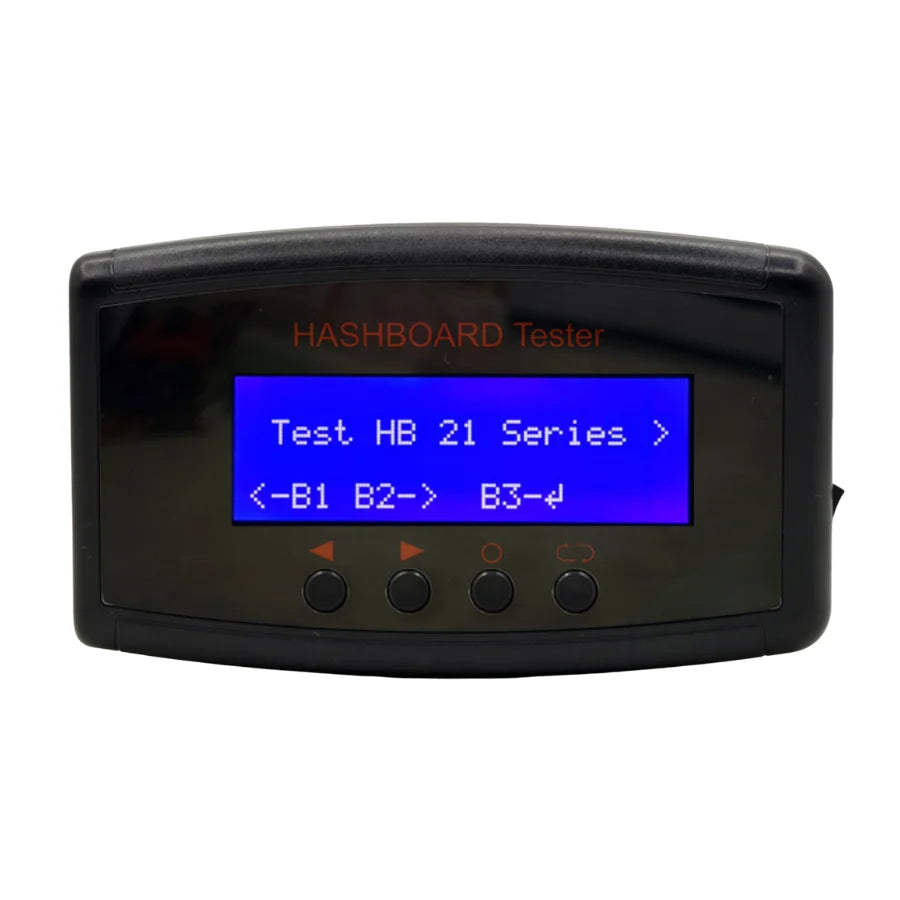
If you're managing more than a handful of miners, a dedicated PSU tester pays for itself quickly. It lets you test APW12 (and APW17) voltage output, load response, and fault conditions without connecting to a miner — isolating whether the problem is the PSU or the hashboard pulling it down.
This is especially valuable for the over-current protection trip scenario: if a PSU shuts down immediately under load, you need to determine whether the PSU's OCP circuit is faulty or whether a hashboard has a short pulling excessive current. A PSU tester lets you apply a known load independently.
The LYS Technical Team is based in Shenzhen, China, where we operate a dedicated ASIC mining hardware repair workshop and parts supply operation. We ship spare parts, repair components, and diagnostic tooling to mining operators in over 40 countries. Every article we publish is written and reviewed by working repair technicians who service Antminer, Whatsminer, and Avalon hardware daily.
Frequently Asked Questions
Can I use an APW121215c to replace an APW121215e?
No. The c version (Group 1: no voltage feedback) cannot replace the e version (Group 2: with voltage feedback). The miner's control board expects the feedback signal. Using a Group 1 PSU where Group 2 is required can prevent the miner from starting or cause incorrect output voltage. Always replace within the same group, or upgrade from Group 1 to Group 2 with a firmware update — never downgrade.
My APW12 blows fuses repeatedly. What's causing it?
A repeatedly blown fuse almost always means a downstream component has failed short — most commonly the MOV (surge varistor) or a primary-side MOSFET. Replace the fuse, then immediately check the MOV for signs of damage (cracking, discoloration) and measure MOSFET D-S resistance for shorts before powering on again.
Is it safe to repair an APW12 myself?
EMI filter components (fuses, MOVs, X-caps) and fans can be replaced by anyone with basic soldering skills — these are low-risk repairs on the input side. MOSFET replacement and auxiliary circuit repairs require board-level soldering experience and an understanding of high-power circuits. The PFC capacitors hold lethal voltage (410–420V DC) even when unplugged — always discharge before working inside the unit.
What's the difference between APW12 and APW17?
The APW17 is Bitmain's next-generation PSU, designed for the S21 and S19j XP. It delivers 12–15V at up to 267A (vs 233A for the APW12) with higher current capacity for the more power-hungry S21 hashboards. The APW17 uses a similar architecture but with upgraded power stage components to handle the higher load. They are not interchangeable — use the PSU specified for your miner model.
How many spare APW12 fuses and fans should I stock?
For a 100-unit operation: keep at least 20 fuses (T10AH250V), 10 MOVs, 10 X-caps, and 10–15 replacement fans on hand. These four items cover roughly 80% of all APW12 failures and cost under $200 total to stock. The alternative — waiting for a full replacement PSU while a miner sits idle — costs far more in lost mining revenue.
APW12 Parts & PSU Replacements
We stock the full range of APW12 consumables and replacement units — fuses, capacitors, MOSFETs, fans, complete PSUs, and PSU testers. All parts are tested before shipping.
→ APW12 12-15V PSU (Complete Unit)
For bulk PSU parts kits or fleet-level repair support, contact us at contact@lys-sz.com or via WhatsApp.